A Comprehensive Guide to Fin Stabilizers on Ships: Components, Operation, and Preparation
Modern ships, especially passenger liners and large commercial vessels, are equipped with fin stabilizers to counteract the rolling motion induced by waves, ensuring smoother sailing and better comfort for passengers and crew. Positioned on the lower part of the ship's hull, these stabilizers play a crucial role in stabilizing the vessel by dynamically adjusting the fins to control roll movements.
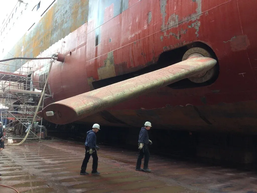
While many seafarers only get to see these stabilizers during dry dock inspections or maintenance surveys, having a detailed understanding of the system is essential for marine engineers and ship officers.
Main Components of a Ship’s Fin Stabilizer System
A fin stabilizer is more than just the fin protruding from the hull—it is a complex system with numerous mechanical, hydraulic, and electronic components working in tandem to ensure smooth operation. Let’s take a closer look at the components that form the backbone of this system.
1. The Fins
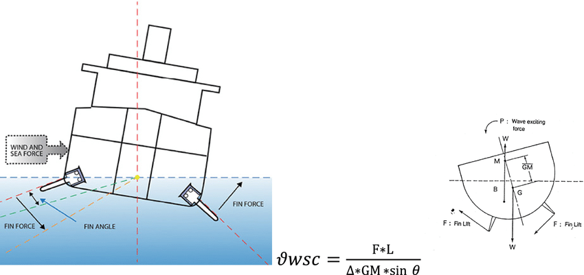
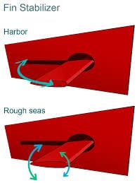
- Each ship is equipped with two fins—one on the port side and one on the starboard side. These fins are designed to rotate and tilt to counter the rolling movement of the ship.
- The fins are housed in fin boxes, which are connected to stabilizer rooms on either side of the ship. The machinery inside these rooms enables the fins to move in and out and tilt to angles of ±25 degrees to counteract roll.
2. Hydraulic Power Units (HPUs)
- Each fin stabilizer has a dedicated HPU located in the stabilizer rooms on the port and starboard sides. These HPUs supply the necessary hydraulic pressure to perform fin tilting and rigging movements.
- The primary HPU consists of a high-power electric motor that drives a variable delivery piston pump. This pump regulates the hydraulic pressure required for smooth operation. The HPU also has a tandem vane pump to provide control pressure and an auxiliary vane pump for pump replenishment and rigging operations.
3. Bridge Control Panel (BCP)
- The BCP, located on the Bridge Machinery Control Console (BMCC), serves as the primary remote control for the fin stabilizers. The ship’s officers use this panel to operate the stabilizers while monitoring their status during navigation.
4. Local Control Units (LCUs)
- Each stabilizer room contains an LCU to provide local control and monitoring. If remote control from the bridge becomes unavailable, engineers can operate the stabilizers directly from these units. LCUs also display fin status indicators, allowing quick troubleshooting during maintenance or inspections.
5. Main Control Unit (MCU)
- The MCU, located in the Engine Control Room (ECR), mirrors the functionality of the Bridge Control Panel, providing an alternative control point. In case of communication failure with the bridge, operators can switch control to the MCU via a selector switch.
- The MCU displays the operational status of both the port and starboard stabilizers and allows for detailed monitoring and control from the ECR.
6. Roll Motion Sensor Unit (RMSU)
- The RMSU measures the roll acceleration of the ship and sends control signals to the stabilizer system for roll correction. This unit plays a critical role in real-time stabilization by feeding data into the system's control algorithms.
- The RMSU consists of a solid-state sensor and signal conditioning electronics, which are integrated into the MCU.
7. Fin Angle Feedback Transmitter
- This transmitter monitors the current tilt angle of the fin and sends feedback to the servo controllers to ensure precision in operation.
- It is mechanically coupled to the tilt cylinder’s piston rod and provides real-time information on the fin’s position to both the bridge and engine room operators.
8. Stroke Control Unit (SCU)
- The SCU is mounted on the variable delivery pump and is responsible for controlling the pump’s spindle position. It ensures that the correct hydraulic flow is provided for the required fin movement.
- The SCU contains a servo motor with gears and an integral resolver for precise control, ensuring that the pump’s flow rate matches the rotational speed required for the fins.
How the Fin Stabilizer System Works
The operation of the fin stabilizer system involves several synchronized actions between hydraulic, mechanical, and electronic components. Below is a detailed breakdown of the system’s working process.
1. Powering the Fins Using the Hydraulic Power Unit (HPU)
- The HPU drives the tilting and rigging movements of the fins using hydraulic pressure.
- The variable delivery piston pump regulates the tilt of the fin by adjusting the hydraulic flow. A rotary valve, controlled by the SCU, modulates the flow rate. This ensures smooth and proportional fin movement.
2. Controlling Fin Rigging and Emergency Operations
- Fin rigging—the movement of the fin in and out of the stabilizer box—is managed using solenoid-actuated valves.
- In case of an emergency, the system can use a secondary electric motor connected to a constant delivery gear pump to stow the fin to a zero-degree angle. This auxiliary motor ensures that the fin can be safely rigged even if the main motor fails.
3. Remote and Local Operation Options
- The stabilizer system can be operated from the Bridge Control Panel (BCP) or the Main Control Unit (MCU) in the engine room.
- A selector switch on the MCU allows operators to switch control to the ECR if communication with the bridge becomes defective.
- Local Control Units (LCUs) in the stabilizer rooms allow for direct control of the fins for troubleshooting or maintenance.